The key factor of CNC Machine Shop:- CNC Machinist
Machinists like to live on the edge, but they always want to
know precisely where it is. If you've watched machining videos (* cough *),
then you've seen heavy use of digital readouts on machines. A "DRO"
(as the cool kids call them) is a small computer that knows where the slides
are, and therefore where their cutter is in the room. However, there is a
catch. DROs do not know the +absolute position of the spindle, they know the
relative position of the spindle. The bottom line is that a DRO is just a sleeker
version of the graded scales on the handwheels. The key difference is that the
DRO does not experience a violent reaction, as it measures the slides directly
(through glass scales similar to its digital caliper) rather than inferring the
position of the lead screw rotations. With traditional handwheels, you must
compensate for kickback every time you change direction, and a DRO saves you
from that (among other convenient features).
The point is, whether it's old school or new, you only get a
relative coordinate system from you. You need to establish an origin somehow. A
useful way to do this is to set an origin to a corner of the part, based on its
physical edges. How do you tell the DRO (or hand wheels) where the edges are?
Enter the edge finder.
Precision beyond Measurement:
 |
| Image Source - Google/ Image by -https://mfgtechno2020.blogspot.com/ |
Accuracy beyond measurement
The humble edge finder is one of those tools that are so
common in manual machining that everyone has forgotten how smart they are. It's
just an axle with a precision chunk of the ground at the bottom that can float
laterally (with some spring tension). This shaft has a precise (and known)
diameter, usually, something conveniently halved like 200,000 or 6mm. You will
see why this is important in a moment.
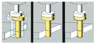
Diagram showing the basic principle of an edge finder. Note
that what is shown here does not use the 2: 1 end-to-spindle ratio, but the
functionality is similar. [Image source: Hoffmann Group]
When thrown into the mill, the edge finder chunk wobbles
like crazy, because it's free to do it. To use it, run the spindle at moderate
to high RPM (say 1000) and bring the wobbly end to the workpiece. As the edge
finder contacts the part, the wobble end will become more and more concentric
with the tool axis.
Step 1: Loose end of tool wobbles freely Step 2: Tip becomes
concentric when approaching edge
So here is the trick, and what makes the device so smart. In
principle, when the oscillating end accurately touches the surface, the edge
search tool will work perfectly concentric. However, that is almost impossible
to see with the naked eye. If it is close but not entirely concentric, you may
not know it. To avoid that, the tension in the spring holding the swing end is
calibrated so that the rotating surface "grips" the part and gains
traction as it becomes concentric, causing it to roll to one side while trying
to roll along. the surface. This is visible when the wobbly end
"kicks" to the side. Here is some technique to get a perfect reading,
because if you continue to rotate the table beyond that moment, your reading
will not be accurate. However, with the proper technique, this very simple
device is extremely accurate and repeatable.
 |
| Image Source - Google/ Image by -https://mfgtechno2020.blogspot.com/ |
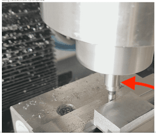
Moving Halfsies from tip to spindle Step 3: When the tip
"kicks", you have located your edge. Offset the diameter of the edge
finder tip and you're ready to go!
Once you have found that edge, you know that the edge of the
tool and the edge of the material is in the same place. However, what you want
is for the center of the tool (and therefore its spindle) to be on that edge.
This step is easy because, as we said earlier, the diameter of the edge finder
tip is known. Just pick up the tool from the job and continue moving in that
direction by the radius of the tool (as shown on your flywheel or DRO). You can
now set your DRO (or steering wheel) to 0 in that dimension and repeat it in
the other dimension. It now originates from a known location and, by extension,
a coordinate system throughout the part. There are many types of edge finders
(including electronic ones commonly used in CNC), but the basic cylindrical drum
type is common, inexpensive, and accurate. Three things machinists love!
Avoid stacking tolerance
A final note: when making your own mechanical drawings, it
is always useful to choose a corner of each surface to mark all its dimensions
and locations. Edge searching is one main reason why. If all of their numbers
are relative to the same corner, the machinist only has to search for edges
once, and there will be fewer accumulated errors when resetting the origin.
Either that or the engineer has to do mathematical calculations to recalibrate
all the numbers he gave so that they are relative to the same place. Both
scenarios will make said machinist angry. Help bridge the generation gap
between engineers and machinists by thinking about where they came from. If you
don't, hope to one day find a spanner on the wrong side of your broken window.


Post a Comment
Hello everyone, if you have any doubts, a suggestion for our blog so please comment.